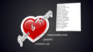
 The Variable Data Wizard is useful for things like quickly and easily replacing text in a workspace. Things can get complicated if that text has associated cut lines, but with contour cut settings in VDW, you’ll be able to replace text and have your cut lines automatically set to fit the new text.
To start, we’ll go over functions such as Inside/Outside contour, Offset, and Corner style. We’ll also explain the threshold transparency filter.
To access the Variable Data Wizard or VDW:
- Right click on a job loaded into the queue.
- Select Variable data wizard.
- Select the graphic with the select tool located on the top of the tools to the left.
Once the graphic is selected the VDW tool icon becomes active. Click on this icon and the smart bar on the top will populate with settings for the contour cut. On the left, you can select Inside/Outside. When ticked, it will give you a contour cut on the outside as well as any holes in the design on the inside.
Unticked means the contour cut will be created on the outside only. Below this box is the Bitmap frame option where the frame of the bitmap file will be used as the contour cut line. In the center you can define the color, corner shape, the offset of the contour cut, and a bleed vector amount. On the right we have a Merge function for Labels.
Next, set your options for working with the cutlines:
- Ensure the correct use of the Inside/Outside box is selected depending on where you want your cutline.
- Set the correct amount of offset.
- Click apply.
After these options have been selected, the Monochrome Filter dialog will open. This is where you can define what is seen as white. 255 is pure white. If you work with a white background, in most cases you want to have the value set between 245 and 255.
Once you click apply, a Contour Cut will be applied to the job. Deselect the graphic by clicking somewhere outside the object. The smartbar will change and you will see a button on the right to send it to the queue. Click Send to Queue and job is now ready for print and cut. You can see by the icon to the left of the job that it now is ready for contour cutting.
In this next example we will take a closer look at the Contour Cut settings starting with contour inside/outside and bitmap frame.
Once in VDW, click on the graphic and click the Contour Cut Icon to the left. Change the contour cut line colour to red by selecting the color picker in the smartbar and choosing red.
With these cuts, you can opt for:
- Outside
- Inside/Outside
- Bitmap Frame
styles of contour cuts. With Outside only, the cutline appears off the outside of the graphic. With the Inside/Outside ticked, the cutlines can be seen only on the outside but also in holes on the inside. Finally, using Bitmap Frame, the cutline follows the outside perimeter or bounding box of the full graphic file.
You can also define the Corner Style, the Colour, and the Offset of the contour cutline found in the middle of the smartbar.
Using the sharp corner style, you can see the sharp corners in the contour cutline. With the round corner style, you can see that the corners have been rounded. The mitred corner style creates edges on the corners.
When working with a file that has semi-transparent areas, you can adjust the values in the monochrome filter, which allows the contour cutting feature to interpret a lesser value of transparency as fully transparent. The contour cuts will appear closer to the graphic. You may need to try a few times to get the offset that looks best for your design.
If you want to learn more about contour cutting in VDW, check out our video below: